Because I am a beginner and my heart was to eager to start AVR programming, I ended up buying a few ATmel chips but no AVR programmer.. I had a hard time understanding why I needed such devices to start programming.. Honestly, at first I believed that programming ATmel chips were pretty much the same as dealing with Arduinos where you only need a USB cable. I mean, its the 21st century people! Nobody uses CD-ROMS and serial ports anymore… the world uses USB, HDMI these kind of stuff. I was naive to believe that Atmel chips would provide such interfaces at the basic level.
Anyhow, since it was going too take me a few more weeks for the AVR programmer that I ordered on ebay, I tried to find another way to program Atmel chips and I found it: using Arduino as an AVR programmer.
The post that I found is here. It was exactly what I needed and the movie is very helpful. But still, it does lack some critical information that would have been better if discussed more thoroughly. This is what I intend to do here. Give a more detailed explanation because beginners like me don’t fully understand what the experts are saying.
In this series of posts, the main purpose is to give a detailed walkthrough on how I managed to set my Arduino UNO so that I can program an Atmel chip. However, the underlying purpose of this is to give a general understanding of how the AVR programming works which is critical for anyone who intends to start AVR. I know that these things look really complicated(especially the makefile stuff…) but if you understand the principle, you’ll find that it isn’t such a big problem after all. Of course I’m not an expert myself so I may not be giving you the best answers but I hope my walkthrough will help other novices because the experience that I’m about to write down is purely in a ‘novice’ perspective.
So for the very first post, lets cover the basic(a.k.a ‘boring’…) but essential concepts that any beginner SHOULD understand. The explanations that I’m giving is quite ‘non-expert’ but I guess this version would be more familiar with beginners like you.
This post is very much intertwined with other posts in my blog. I just thought it would be better to divide the basic stuff into several parts.
Here is a list of contents:
- what is an avr programmer
- how the ‘compiling’ works
- setting up arduino to work as an avr programmer
- actual compiling example
What is an AVR programmer
I mentioned that I made a mistake of thinking that atmel chips basically provided usb connection but it didn’t. In order to ‘insert’ the code to the chip, I think its suffice to say that you pretty much need three things:
1) ATmel chip (of course…)
2) AVR programmer
3) AVR compiler and other software stuff that will run on a PC.
When I was understanding this concept, I had difficulty understanding 2). The word ‘programmer’ does make it sound like it is a software and not a hardware. But actually, ‘programmer’ corresponds to a cable-like device that will allow compiled program to be transferred to the Atmel chip.
Here’s a link that explains about these ‘programmers’: http://www.ladyada.net/learn/avr/programmers.html. This page introduces JTAG, but I’m not yet ready for this so I skipped this part. What made me wonder was the difference between the ‘simple/bit-bang’ programmers and ‘smart’ programmers. I asked this in a really good AVR community, AVRfreaks: click. Key point: bit-bang is for ancient PCs so don’t even think about it. ‘smart’ deviates from the fact that ‘smart’ programmers has some kind of chip that will enable to convert usb data communication into bit-band which the atmel chip does understand. So, most of the ‘AVR programmers’ that you will find at a store will probably be a ‘smart’ programmer.
How the ‘Compiling’ Works
Now lets take a look at 3). If you’ve ever done some googling about AVR programming basics, you probably would have encounters IDE for AVR programming.. ‘WinAVR’, ‘AVRdude’, ‘AVRstudio’ etc… Honestly, I don’t know and didn’t try all of them. All I tried was WinAVR for Windows OS, and a bundle of programs in my Ubuntu. I never found the ‘one’ webpage that explains all of these softwares but here are some links that you might find useful.
http://www.ladyada.net/learn/avr/avrdude.html
http://www.youtube.com/watch?v=bEfjFJlrGxs
http://www.youtube.com/watch?v=wfQBS22jxL8
http://electronics.stackexchange.com/questions/66145/avr-how-to-program-an-avr-chip-in-linux
But whether you use WinAVR or a bundle of programs in UNIX, you have to understand the fundamental processes that happen when compiling and eventually putting your program into the chip. For that, you need to have a better understanding at ‘compilation’. If you have studies computer science, then you might not even need to read this part. But for non-advanced geeks like me, it is very helpful to first see what the compilation looks like.
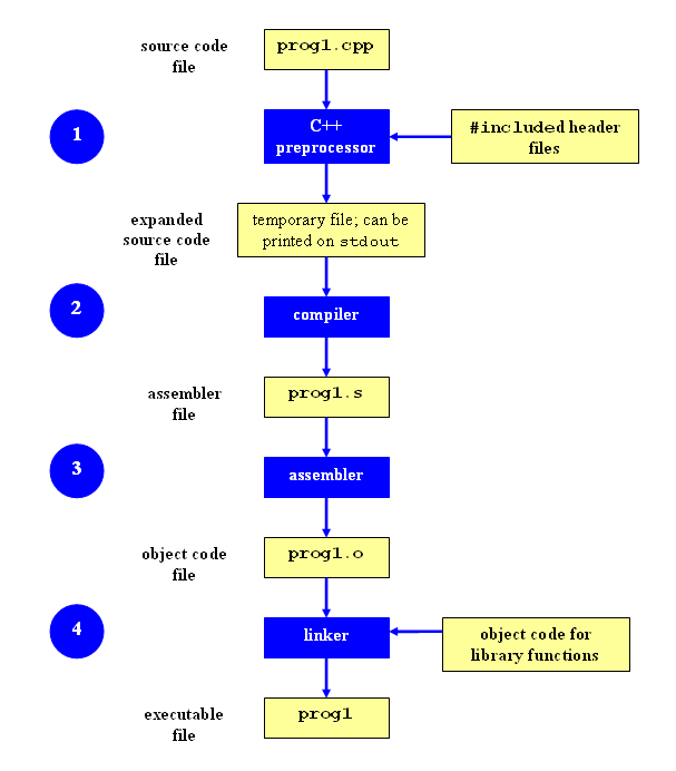
The C language that we humans type in are human-friendly languages. On the other hand, the machines need the human-friendly code translated to machine-language in order to properly execute the orders written in the code. The following diagram shows how this ‘translation’ process is done.
 |
| src: http://faculty.cs.niu.edu/~mcmahon/CS241/Notes/compile.html |
After looking at the diagram I guess I was ‘techically’ wrong to say ‘compiling’ means all of these steps when it actaully was only one part of the steps.
FYI, the ‘xxx.o’ which refers to object files also has another extension named ‘xxx.elf’. The ELF file is an object file format used in UNIX systems. You’ll see these file later on when using WinAVR.
for more info about compilation, check out some websites:
http://www.tenouk.com/ModuleW.html
http://www.linuxjournal.com/article/1059
I don’t know exactly what assemblers, linkers, object file are for sure, but for our purpose of compiling AVR programs, I think its okay to compress and comprehend the process of compilation into two steps:
1) preprocessing & compiling & assembly: XXX.c → XXX.elf
2) linking: XXX.elf → XXX.hex
The reason why we can think of it into these two steps will become clear once you have reached to the next part. But for now, just understand that the whole avr compilation can be divided into these two steps.
Its fine to think of xxx.elf as an intermediary and the xxx.hex file as the final result that we have to flash to the atmel chip. I’ll stop giving more details because its getting pretty messy already and you can always dig further on your own with google.
So the final result of compilation is the ‘executable file’ according to the image above. In AVR programming, this executable file will be in ‘.hex’ format where all the code is consisted of zeros and ones. We all learned that digital devices will operate by processing zeros and ones. Well guys, the .hex file is the real thing that the devices really do understand.

Setting up Arduino to Work as an AVR Programmer
OKAY, I say that we’ve done enough with the plain texts and theories. Its time to do some action! In the beginning of this post I gave you a post that I originally started with: url-link. This post is really good and you might even actually end up succeeding AVR programming with this if you’re lucky. I recommend that you DO take a look at this post and PATIENTLY watch the video without skipping. If you feel like it follow the video yourself.
Here, I’ll give a walkthrough with my arduino & breakboard setup.
First, lets setup the arduino to act as an AVR programmer. The AVR programmer uses ISP(In-System-Programmer) to download the code from the PC. There are two types of ISP pin configuration: 6pin, 10pin.
 |
| src: http://pepsiman.tistory.com/45 |
As you can see from the image, you can see that 10 pin is just 6pin+3 GNDS+NC. I don’t know what NC is for but it doesn’t matter in this tutorial. If you want to know more about the exact funtionality of each pins, find out for yourself.
Back to arduino: if you are an arduino user, I’m sure that you already have the ‘sketch’ program installed. Connect your arduino to your computer and open sketch.
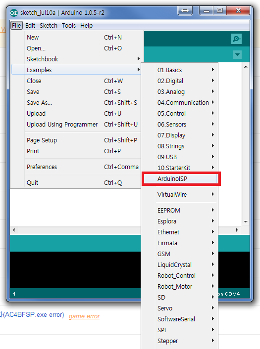
Another sketch window with the code will appear. At first sight, you see some familiar words: MISO, SCK, RST.

These arduino pins should now be connected to the ATmel chip pin that corresponds to MISO, MOSI, SCK, RST.
Oh by the way, right at the bottom of the red-boxed part, you can read that arduino pin 9 will give out a heartbeat-like signal to show that the ArduinoISP code is running perfectly. It’s best to connect and LED bulb+small resistor to this pin for later use.
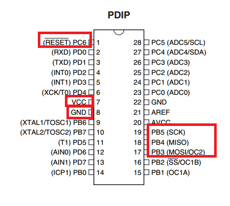
In my case, I have an “ATmega8-16PU”. I downloaded the datasheet for this model from ATmel.com. At the beginning of the datasheet, I got the pin layout which looks like this:
Actual Compiling Example
Since I’ve discussed about the compilation previously, lets check out the commands that actually does these compilations. The commands that will appear in the following are going to be crucial for those who want to do their AVR programming in UNIX systems. Does this mean that Windows users using WinAVR don’t need to know this? Yes they also certainly do. You see, WinAVR is just a bundle which does all of this compilation in the Windows system so if you look inside what WinAVR does, its actually doing the same thing that a user should do in linux environment. So if something goes wrong during the compilation with WinAVR, the window user eventually have to get their hand dirty with the compilation commands which makes them on the same line as the unix users.
Where I present you two ways to do it: (click to go to another post to check them out)
1) installing and compiling WinAVR in Windows
2) installing and compiling in Ubuntu(or other UNIX env.)
